OEM Best Impulse Voltage Test System Suppliers – GDCY-300kV/30kJ Impulse Voltage Test System – HV Hipot
OEM Best Impulse Voltage Test System Suppliers – GDCY-300kV/30kJ Impulse Voltage Test System – HV Hipot Detail:
Application
This impulse test system is used for carrying out full wave lightning impulse voltage tests on HV apparatus such as clearance, bushings, capacitors, switches, power transformers(capacity below 5000kVA), CT/PT at 35kV or below.
Operating Condition
● Altitude: 1000m.
● Ambient Temperature: -5℃~+45℃.
● Max. daily difference temperature: ≤25℃.
● Relative humidity: <90%.
● Anti-shock ability: ≤ level 7.
● Horizontal acceleration of the ground: 3.0m/s2, Vertical acceleration of the ground: 1.5m/s2.
● Waveform of power supply voltage wave is sine actually, and the waveform distortion rate<3%.
● It should be grounded reliably, ground resistance <0.5Ω.
● Usage environment: indoor. No conductive dust, No fire and explosion, No corrosive metal and insulation gas.
Applied Standards
IEC60-1 <High Voltage Test Technique>
GB7449 <Test Guideline of lightning impulse and switching impulse for power transformer and reactor>
GB1094.3 <Power Transformer>Section 3: Insulation level and insulation test
GB/T 311.1 <Insulation and coordinate of High Voltage Power Transmission and Distribution>
GB/T 16927.1 <Technique of High Voltage Test>-Section 1: General Requirements
GB/T 16927.2 <Technique of High Voltage Test>-Section 2: Measurement system
GB/T 16896.1 < Digital recorder of High Voltage Impulse Test>
ZBF 24001 <Implementing Rules of impulse voltage test>
GB/T 11920 <General Technical Condition of Central Control Device in power station>
GB/T 191 < Packing&Storage graphic symbol>
DL/T846.1 <General Technical Condition of High Voltage Test Equipment>Part 1: High Voltage Divider Measurement System
DL/T848.2 <General Technical Condition of High Voltage Test Equipment>Part 2:
Power Frequency High Voltage Test Equipment
DL/T848.3 <General Technical Condition of High Voltage Test Equipment>Part 3:
Partial Discharge Testing Transformer
DL/T848.5 <General Technical Condition of High Voltage Test Equipment>Part 5:
Impulse Voltage Generator
Rated Parameters
● Nominal voltage: ±300kV
● Rated energy: 30kJ(5kJ/stage)
● Impulse capacitance: 0.666µF
● Number of Stage: 3
● Charging voltage per stage: ±100kV
● Rated level capacitance: 2µF (each impulse capacitor 2µF at 100kV, total 3pcs)
● Output voltage waveform: (Load capacitance is 300-3000pF)
T1= 1.2µs±30%, T2=50µs±20%, peak voltage error≤3% standard lightning impulse voltage full wave.
● Impulse voltage waveform parameters and error are accorded with national requirements of GB311.1and GB16927.1 standard and IEC standard.
● Output Voltage Efficiency: Standard lightning wave ≥90% when load capacitance is below 1000pF, standard lightning wave ≥85% when load capacitance is below 2000pF.
● Locking range: level voltage is within the range of 20%-100% of rated voltage, positive and negative locking range no less than 25%.
● Out-of-control rate of synchronous discharge: <5%
● Min.output voltage: ≥±10% of rated voltage.
● Instability of charging voltage: <±1.0%
● Continuous time: Above 2/3 of rated voltage, continuous working when charge and discharge once every 120s. Below 2/3 of rated voltage, continuous working when charge and discharge once every 60s.
System Configuration
1. Charging Device
● Constant current charging device, rated output voltage±100kV, rated output DC current 10-100mA.
● Oil type charging transformer, primary voltage is 220V, secondary voltage is 50kV rated capacity is 5kVA. No oil leakage of transformer.
● 2DL-200kV/100mA HV rectifying silicon stack (HV diode), reverse voltage200kV, average current 0.1A. HV diode is installed on the charging board.
● Protective resistor of HV diode is made of enameled resistance wire.
● Instability of charging voltage <±1% at 15%-100%rated charging voltage of constant charging device. The adjustable accuracy of charging voltage is 1%.
● DC resistance voltage divider 100kV, 200mΩ, with HV vitreous glaze resistor. LV resistor is installed at the bottom of divider, while the voltage signal of LV side is lead to measurement system by shield cable.
● Automatic earth switch is open and close by electromagnet. Automatically short-circuit main capacitor and ground by protective resistor when testing stops.
● Charging transformer, HV silicon rectifier, resistance divider, charging current-limiting resistor and main controller are installed in the same movable chassis.
● The device is not only used as charging power supply of impulse voltage generator, but also as DC voltage generator to generate 100kV DC voltage, which can be used in DC test for other apparatus.
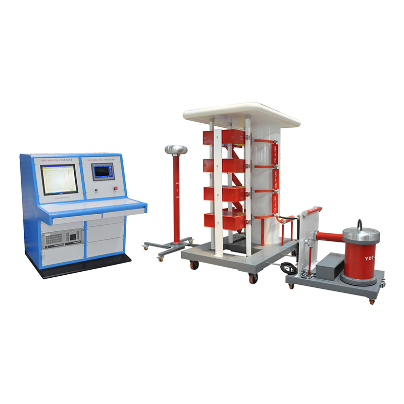
2. Impulse Voltage Generator

● The generator is ”H type”.
● Voltage boosting charging loop circuit, each level rated voltage is 100kV.
● 3levels tower structure for insulation support. Each level includes 1 piece MWF100-1 metal-shell oil type pulse capacitor, charging resistor, front wave resistor, end wave resistor and ignition sphere gap. When lightning wave is generated, select suitable wave-front resistor, wave-end resistor and stage according to the capacitance of test object.
● Stage pulse capacitance is 10.05F, DC working voltage is ±100kV, capacitor rest inductance 0.15μH. The vertical tension to be withstand for the lead-out bushing of capacitor is 15kg. It ensures no damage and oil leakage.
● Front wave resistor, end wave resistor are all slab structure, reeled without Inductance.
● Connectors are spring pressure welding type, which is reliable contact and convenient for plug-in and out in wave adjustment.
● Bracket of wave-front and wave-end resistor can be used for several resistors in parallel.
● The 1st sphere gap is triggered by doubling piece heteropolarity. The 2nd to 3rd sphere gap are ignited with three gaps sphere gap, ensure reliable triggering.
● The distance of each level sphere gap is linear adjusted by permanent magnet motor.
● Sphere gap distance can be adjusted by manual.
● Every 2levels or multi-level can be used in parallel.
● The support is made of fiberglass reinforced plastics. Part of the highest potential is anti-age and anti-corona.
● Each level is anti-corona. No obvious corona during charging.
3. 300kV Weak Damped Capacitive Impulse Voltage Divider
● There is single capacitor in HV (high voltage) arm.
● Rated is 300kV/600pF.
● Rated lightning impulse withstand voltage is 300kV.
● Voltage ratio: 1000:1
● Uncertainty of range factor: Kε≤1%
● Overshoot: β≤20%
● Response time: Tα≤100ns
● The square wave of Weak Damped Capacitive Voltage Divider meets requirement of GB311 standard
4. Chopping Device (Special for transformer test)
The multi-level gap chopping device is composed of 2pairs of discharge sphere gap. It is movable. If connecting with control unit, it can remote control sphere gap. It is stable and it has the function of adjusting delay ignition triggering controlled by electronic circuit.
● Nominal voltage: ±300 kV
● Chopping time: 2-6μs
● Standard error of chopping time: <±0.1μs
● Adjusting range of chopping time: 0-9.9μs(delay signal is sent by control system)
● Quantity of sphere gap: 2pairs(4pcs)
● Triggering mode: 3 sphere gap discharge triggering
● Delay mode: Using LC time-delay circuit, used together with control system.
5. Control Unit (PLC)

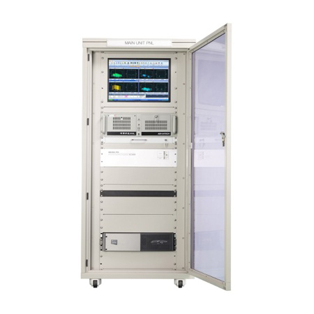
PC intergrated the measurement and control function together.
● 15′ LCD screen
● Tektronix oscilloscope and the PLC programmable control is from GE company, with GE Faunc 12digit AD switching module.
● The signal transmission between control unit and generator is optical fiber. It has bi-directional signal processing function.
● Waveform display, analysis, mapping, printing and etc functions.
● Setting measurement parameters according to high voltage test, then automatic setting the digital oscilloscope accordingly.
● Calculate the waveform parameters automatically, accorded with IEC1083 standard.
● With anti-interference technology.
● Control interface can indicate first level charging voltage (accuracy: 1.0%), the real time distance of generator sphere gap and chopping wave sphere gap.
● Triggering chopping wave delay time: 2-6μs
● Deviation of chopping time: <0.1μs
● Adjustable range of ignition pulse delay time: 0-9.9μs
● Ignition impulse amplifier to generate impulse voltage >15kV/100nS
● Over-voltage/over-current protection.
● To control the operation of Impulse voltage generator, complete the normal charging and discharging, all the parameters operated and real time monitored by PC.
● Automatic control or manual control is optional.
● Interface to display the status of generator, including grounded or ungrounded, charging speed, numbers of level, charging voltage, sphere distance and etc.(automatic control)
● User to adjust the distance sphere gap, switch charging polarity, send triggering impulse via the interface.(manual control)
● Control the distance of discharging sphere tracking charging voltage by manual or automatic. Display the distance value of discharging sphere.
● Control unit grounded automatically.
● Control and display the distance of chopping wave sphere.
● Impulse times presetting and automatic polarity changing functions.
● Automatic alarm.
● Constant current charging. Adjust charging voltage and time according to the test requirement and display the charging voltage value. Charging stability: 0.3%.
● Charging speed: fast and slow can be selected.
● Using manual, automatic or alarm mode to trigger ignition.
● Safety interlock control. It has fully alarm function and control interface, also automatic grounding, safety grounding and system interlock. With over-current and over-voltage protection function, emergency stop function.
● Extended function. It can be communicated with PC by serial port.
● The measurement control table is desk type. The monitor, keyboard, mouse and printer are placed on the desk. The mainframe of PC, oscillograph, isolation filter power supply, UPS are placed inside the desk. The relay, PLC, over-voltage and over-current protection components are placed on the bottom of generator.
● The measurement system is Tektronics TDS-1102B oscillograph. The banwidth is 100MHz, max. Sampling rate 2GS/s, record length 2.5k, 2 channels. It records lightning full wave, switching wave and lightning chopping wave.
● The system can finish all measurement of impulse voltage as below table 1, and measurement error and system waveform parameters analysis function as below table 2. The software is evaluated by IEC61083-2.
Table 1 Impulse voltage waveform and parameters
| Waveform | Parameters |
| Lightning impulse | Peak value Wave front time Half-wave peak time |
| Lightning impulse chopping wave | Peak Wave front time Chopping time Zero coefficient |
Table 2 Uncertainty of measurement system (including divider)
| Impulse wave type | Uncertainty of measurement system(including divider) ke£ % |
| Lightning wave, chopping wave, switching wave | 3 |
Typical measurement function includes
● Impulse Voltage Measurement and waveform analysis: 2channels, max. Sampling rate 2GS/S
● Waveform comparison and offline analysis: the waveform can be saved by .DAT file and it will be read and displayed on the screen, to help user to compare different impulse waveform.
● Test report digitization: the test report can be written on the designed test report template. It can input words, draw and insert circuit wiring diagram and waveform. The report can be saved and printed.
● Time-base waveform display: the waveform data of each channel (such as voltage and current waveform) will be displayed independently based on different time-base. It is easy for users to analyze waveform.
Specifications of Control System
● Adjusted range of charging voltage: 0.0-100.0kV
● Charging voltage: 10.0-100.0kV
● Adjustment accuracy: 1%
● Instability of charging voltage: <1%
● Setting range of charging time: 30-60s
● Adjustment accuracy of charging time: 10s
● Alarm delay time: 2s
● Triggering impulse delay time of chopping wave: 0.0-9.9μs
● Adjustment accuracy of delay time of chopping wave: 0.1μs
● Setting times of impulse test: 0-99times
● Adjustment accuracy of impulse test times: 1times
● Input voltage: 10-380V AC continuous
● Output current: 0-100A AC
● Double-shielding measurement cable.
System composition
| No. | Name | Description | Qty | |
| 1 | Impulse Voltage Generator | 300kV/30kJ | 1set | |
| 2 | DC Charging Device | Bilateral asymmetric, constant charging | 1set | |
| 3 | Weak Damped Capacitive Divider | 300kV/600PF | 1set | |
| 4 | Chopping device | 300kV | 1 set | |
| 5 | Measurement and control system | 1set | ||
| 6 | Measurement unit | Tektronix oscillograph 1102B | 1 set | |
| 7 | Earth Stick | 2M, including flat type copper wire 5M | 1set |
Product detail pictures:
Related Product Guide:
Our goal is usually to deliver high quality items at aggressive price ranges, and top-notch service to shoppers around the entire world. We're ISO9001, CE, and GS certified and strictly adhere to their high quality specifications for OEM Best Impulse Voltage Test System Suppliers – GDCY-300kV/30kJ Impulse Voltage Test System – HV Hipot , The product will supply to all over the world, such as: Greece, Bahrain, Mexico, So We also continuously function. we, focuse on high quality, and are conscious of the importance of environmental protection, most of the merchandise are pollution-free, environmentally friendly products, reuse on the solution. We've Updated our catalog, which introduces our organization. n detail and covers the primary items we provide at present, You may also visit our web-site, which involves our most recent product line. We look forward to reactivating our company connection.
The company can think what our think, the urgency of urgency to act in the interests of our position, can be said this is a responsible company, we had a happy cooperation!

