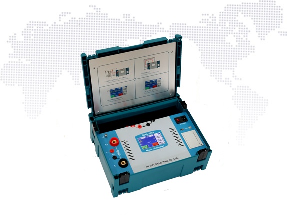
When the loop resistance tester (also called the contact resistance tester) designed according to the traditional design principle was tested in the field, it was found that there was a common problem. When the voltage connection circuit of the tester is in poor contact or open circuit, the tester will also display a value, and the following situations will occur:

HV HIPOT GDHL-200A/100A Automatic Loop Resistance Tester
(1) The voltage loop is open, and there is no strong electric field interference at the test site. In this case, since the differential mode voltage input by the amplifier is basically 0, the test value displayed by the instrument is close to 0. If the tester has enough field test experience, it can judge that the abnormal test line of the instrument voltage circuit is abnormal and return to the instrument voltage. After the abnormal test path is excluded, the final correct test result can be obtained.
(2) The contact of the voltage circuit is poor. In most cases, the terminals of the circuit breaker will produce oxide film or oil film on the outer surface of the terminal after long-term operation. When voltage test clamps for circuit resistors are clamped to such terminal strips, poor contact is possible. When the voltage test clip itself also produces a certain contact resistance, the contact resistance value is the same as the internal resistance value of the voltage sampling circuit. will have a serious impact on the test results.
(3) The voltage loop is open circuit or the contact is poor (when the circuit is open, it can be seen that the contact resistance r1 is infinite), and there is strong electromagnetic interference at the test site, such as a live bus. At this time, the live bus passes through the capacitor with air as the medium, interfering with the two voltage test lines of the tester. Due to interference, the voltage acquisition lines of the loop resistance tester are two. The differential mode voltage appears at the end.
Post time: May-23-2022
