The no-load test of the transformer is a test to measure the no-load loss and no-load current of the transformer by applying the rated voltage of the rated sine wave rated frequency from the winding on either side of the transformer, and the other windings are open-circuited. The no-load current is expressed as the percentage of the measured no-load current I0 to the rated current Ie, denoted as IO.

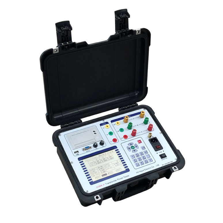
HV HIPOT GDBR series transformer capacity and no-load tester
When there is a significant difference between the value measured by the test and the design calculation value, the factory value, the value of the same type of transformer or the value before the overhaul, the reason should be found out.
The no-load loss is mainly iron loss, that is, the hysteresis loss and eddy current loss consumed in the iron core. At no-load, the excitation current flowing through the primary winding also produces resistance loss, which can be ignored if the excitation current is small. The no-load loss and no-load current depend on factors such as the capacity of the transformer, the structure of the core, the manufacturing of the silicon steel sheet and the manufacturing process of the core.
The main reasons for the increase of no-load loss and no-load current are: poor insulation between silicon steel sheets; short circuit of a certain part of silicon steel sheets; short-circuit turns formed by damage to the insulation of core bolts or pressure plates, upper yokes and other parts; The silicon steel sheet is loose, and even an air gap appears, which increases the magnetic resistance (mainly increases the no-load current); the magnetic route is composed of a thicker silicon steel sheet (no-load loss increases and no-load current decreases); inferior silicon steel is used Pieces (more common in small distribution transformers); various winding defects, including inter-turn short circuit, parallel branch short circuit, different number of turns in each parallel branch, and incorrect ampere-turn acquisition. In addition, due to improper grounding of the magnetic circuit, etc., no-load loss and current increase will also be caused. For small and medium-sized transformers, the size of the core seam can significantly affect the no-load current during the manufacturing process.
When doing a no-load test of a transformer, in order to facilitate the selection of instruments and equipment and ensure the safety of the test, the instrument and power supply are generally connected to the low-voltage side, and the high-voltage side is left open.
The no-load test is to measure the no-load loss and no-load current under the rated voltage. During the test, the high-voltage side is open, and the low-voltage side is pressurized. The test voltage is the rated voltage of the low-voltage side. The test voltage is low, and the test current is a few percent of the rated current. or thousandths.
The test voltage of the no-load test is the rated voltage of the low-voltage side, and the no-load test of the transformer mainly measures the no-load loss. No-load losses are mainly iron losses. The magnitude of iron loss can be considered to be independent of the size of the load, that is, the loss at no-load is equal to the iron loss at load, but this refers to the situation at rated voltage. If the voltage deviates from the rated value, since the magnetic induction in the transformer core is in the saturation section of the magnetization curve, the no-load loss and no-load current will change sharply. Therefore, the no-load test should be carried out at the rated voltage.
Post time: Apr-26-2022
